Video Scope Calibration

A waveform monitor just measures a signal

A software video editor is going to need to measure the output of various manipulations . So in that respect, it’s working as it should - it’s measuring the output node signal of the video editor, not the input file directly

You can use ffmpeg/ffplay -vf waveform too if you need to access files directly ; it’s accurate and measures 8,10,12 bit files correctly, and has many display options and customizations

1 Like

The ffplay scope is pathetic, so I wrote my own. You’ve seen screen shots of it. Actually, I prefer to use the color picker to read colors accurately. I can easily convert RGB values to Y and read them with the color picker.

Again, IRE units are not really applicable to full-range video. I would rather see 235 be 100 IRE than 255 and 16 be 0 IRE. Failing that, I would be satisfied if the graticule were calibrated in 8-bit digital values rather than these pseudo-IRE units.

The newer versions are quite improved - you can change many display settings, digital / ire units, colors, even transparency options to overlay onto your video. It reads YUV directly, and works accurately for 8,10,12 bit. What do you dislike about it, or what suggestions would you have to improve it?

But that 8bit YUV=>RGB=>YUV method is not accurate for real colors (non greyscale). Rounding errors, out of gamut RGB colors are lost; ie. you’re not reading the actual YUV values. You can read actual Y,U,V values with a YUV color picker in vsedit for vapoursynth or avspmod for avisynth (vsedit is better in that it can display >8bit values)

I’d prefer digital code values 0-255 too for 8bit. Some other programs offer both options

It looks to be measuring the converted output for the timeline, not the input video values directly, and based on the properties color range settings (and the flag) .

It’s analogous to the full range equations; it’ s using full range to convert to RGB for display since you have a full range flag - Y 0-255 => RGB 0-255 . 100% black is at RGB 0, 100% white is at RGB 255 . If you change it to limited (or it’s flagged limited, or unflagged), Y16-235 => RGB 0-255. 100% black is still at RGB 0, 100% white is still at RGB 255. But the limited range equations used on YUV video with full range values means that there are Y values that exist below the darkest 0% and brightest 100% that you “see” in the RGB preview. ie. Y<16, Y>235. (They will be clipped by if an actual limited range RGB conversion is performed). If you leave it set to “limited” the video zoom reports the correct Y values would be

Shotcut scope
Again, the problem is not with the scope itself but with the way the graticule is calibrated. Digital 235 should be 100 IRE if you’re going to use IRE units. This is the case with the ffplay scope.

ffplay scope
The ffplay scope is too short on the y axis. Ideally it would be scalable on both the x and y axes. I tried doing this but was unable to make it work.

I am happy to report that in the IRE mode, 235 = 100 IRE and 16 = 0 IRE, so bravo for that. A nice touch would be a custom graticule line where the user could specify the level. This would be handy for setting gamma which is 43.4 IRE on an 18% gray card with 2.2 gamma. Also, I would make the numerals 1 or 2 point sizes bigger.

ffplay windowsignal.mp4  -t 20  -vf waveform=filter=flat:scale=ire:graticule=green:flags=numbers+dots

There is nothing wrong with the “calibration”.

“Limited Range” means the reference black and white level are Y=16,235 . You can still have over/undershoots. This is the “normal” scenario. e.g. broadcast, BD, DVD, web, etc…
“Full Range” means the reference black and white level are Y=0,255

You’re not really dealing with “full range” video; If you want a test video, it should be flagged “limited range” but with over/undershoots . This is the similar to any legal video. So, digital 235 is 100IRE

Next, you’re going to say the RGB preview looks “wrong”. Well, it’s right if you’re using a computer monitor. A reference monitor should be used as the secondary display if you’re using studio range RGB

(FFPlay uses digital 0-255 by default now, unless you are using an old version)

It is scalable - you can chain a vf scale argument. You can overlay it or attach it to your reference video, or stack it against other versions of the video (e.g. maybe an adjusted/color corrected version)

Note: “flat” means you’re combining luma and chroma. By default it’s just luma and digital units. So the short y-axis height is 256 for 8bit video because there are 256 code values; it’s pixel perfect. 1024 for 10bit video so the height is 1024

A custom line is not built into the filter, but you can chain a -vf overlay argument

I don’t think text size can be changed directly, but if resizing still is not sufficient, you can submit a request

As Dan observed, the file I posted WAS flagged as limited range. The 255 patch was showing as 100 IRE. Again, this is not the case with the ffplay scope where 235 = 100 IRE (set “scale” to IRE). So you have the two scopes disagreeing on the same material.

There is no option for “limited range but with overshoots”. You know that.

He also correctly pointed out the Y values were incorrect

No option where?

To make “limited range” with over and undershoots, the actual Y values are the same. Y 0,16,235,255. You just leave it unflagged, or flagged limited range. By default shotcut will assign limited range if it doesn’t “see” the full range flag

You can emulate this right now by selecting color range “broadcast limited” in the properties.

You can create a file like this from scratch, or strip the full range flag. Stripping the flag does not change the actual YUV video data, it’s just VUI information (metadata) when using AVC or HEVC.

eg strip full range flag

ffmpeg -i "WindowSignal.mp4" -bsf h264_metadata=video_full_range_flag=0 -c:v copy "limited.mp4"

I’ll say it again. On my installation of the latest version of Shotcut the values were 0,16,235,255, just like I made them. They were measured off the preview pane with Shotcut’s own video zoom and with my eyedropper and they were both in agreement. I also measured them on VLC and got the values stated above.

I don’t know why Dan was getting screwy values. My values were as stated above. If they weren’t, I would have said something about it.

And yet again, the ffplay scope is AOK. I don’t know why you’re spinning your wheels defending Shotcut’s scope.

For the sake of anyone else reading along and needing a conclusion to how the Shotcut scopes work and whether there are any problems… The scopes are fine. For gritty details, let’s start from the top:

IRE

IRE is a percentage measurement for voltage (implying an analog signal) where 0 IRE is always 0 mV, and 100 IRE is the maximum protocol voltage (usually the whitest white that can be displayed).

This is very dependent on the video specification being used. For NTSC composite signals, a pure black color is 53.57 mV which corresponds to 7.5 IRE. Note that 0 IRE does not automatically mean black. It only means zero voltage, and the meaning of zero voltage depends on the video specification being used.

Fortunately, BT.709 uses a different voltage range than composite video. In the BT.709 spec, table 6.1 shows that black is signaled by 0 mV, and white is signaled by 700 mV. Since black is signaled by limited-range Y 16, this is extremely convenient and intuitive because black = Y 16 = 0 mV = 0 IRE.

At this point, we correlate that 0 IRE means “blackest black” and 100 IRE means “whitest white” for BT.709.

Next, if we think of analog sRGB data going over a VGA cable, we also see that black = RGB 0 = 0 mV = 0 IRE, and white = RGB 255 = 700 mV = 100 IRE.

This makes the meaning of IRE consistent between these two particular color spaces: zero means black, and 100 means white. It works because sRGB was derived from the BT.709 specification, and they both use their voltage maximums of 700 mV to signal white. This IRE equality wouldn’t necessarily happen with other color spaces.

However, an important distinction is that BT.709 IRE as illustrated so far represents limited-range YCbCr (16-235), whereas sRGB IRE represents full-range RGB (0-255). Yet, they land on the same black and white voltages and trigger the same black and white reference values. This is the beauty of the Shotcut scope. It’s possible to graph and match the brightness of clips from different color spaces and ranges provided the black voltages are the same. It is not necessary to have separate graticules for each range. Even if attempted, the graticules would look the same because max white and max black land in the same places for both ranges, as demonstrated above.

BT.709 vs sRGB

A video stream encoded in BT.709 requires conversion to be displayed on a computer using an sRGB video card and monitor. Errors from rounding, out-of-gamut colors, and inaccurate conversion functions are why using a color picker on an RGB display says nothing useful about the YCbCr stream that generated it. The color picker would collect errors from the conversion algorithm. Note that sRGB technically has two range-dependent transfer functions. Quality editors do the full math, but many programs often generalize the curve with one simple gamma conversion. If that happens, the resulting RGB values will not accurately reflect the YCbCr values underneath (especially for darker colors), nor would it be possible to accurately reverse-engineer the video’s Y value from the RGB sample.

Back to BT.709 vs sRGB… conversion is relatively straight-forward because BT.709 and sRGB have the same color primaries and white point, and differ only slightly in gamut and transfer characteristics.

Full vs Limited Range

The BT.709 specification contains both full-range and limited-range equations, although limited range is the only format allowed for over-the-air transmission and most physical distribution mediums. It’s important to know whether results from equations will be in full range or limited range.

To convert RGB values to BT.709 YCbCr, we use the equations in table 3.5 of the BT.709 specification:

D’y = Round(0.2126 Dr + 0.7152 Dg + 0.0722 Db)

Technically, we would not use table 3.2 because E’ refers to the analog electrical part of the chain, but we’re already in digital domain if we’re converting from RGB. Therefore, we use the digital D’ equations in table 3.5 (since we already have quantized RGB values) and the luminance equation happens to have the same coefficients as E’y by design. But the Cb/Cr equations are very different, and this is significant.

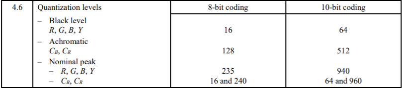
Note that the result of table 3.5’s equations will produce a full-range YCbCr value. As in, RGB 255 pushed through the luminance equation will result in Y 255. In fact, any RGB gray value pushed through the luminance equation will result in an identical value for D’y because the coefficients add up to One (and one times anything is itself). Thus, Y 255 is the way to signal pure white in a full-range video file, and this is the purest form of YCbCr. The math could stop here if it weren’t for the needs of television broadcasters. For their purpose of creating a legalized broadcast signal, we look at table 4.6 which says Y must be compressed (scaled) to 16-235 and Cb/Cr must be compressed to 16-240. This has nothing to do with color purity or conversion theory. Actually, it makes color worse. It’s done because this is a bandwidth precaution taken by the broadcast industry for analog transmissions.

However, Y 235 by itself does not mean white. “Limited range” is a temporary sub-encoding, not a separate and unique specification. To calculate the RGB values needed to activate the pixel components of a TV screen, Y 235 has to be uncompressed to Y 255, where it can then be back-fed through the full-range equations in table 3.5 to get the RGB equivalents. Yes, there are other transforms that consolidate those steps for processing efficiency, but this is what’s happening under the hood.

IRE vs White Point

This is where things gets nuanced, but also very convenient. BT.709 and sRGB use the same white point (CIE D65). For all practical purposes, the following maximal signal values will generate the same visual whiteness on a screen:

  • Full-range Y 255 (the result of table 3.5 equations)
  • Limited-range Y 235 (compression from table 4.6 applied)
  • RGB 255 (assume full range unless metadata indicates otherwise)

Since those are all maximal signals within their specifications, they are also all 100 IRE. And they all look the same because they’re all D65.

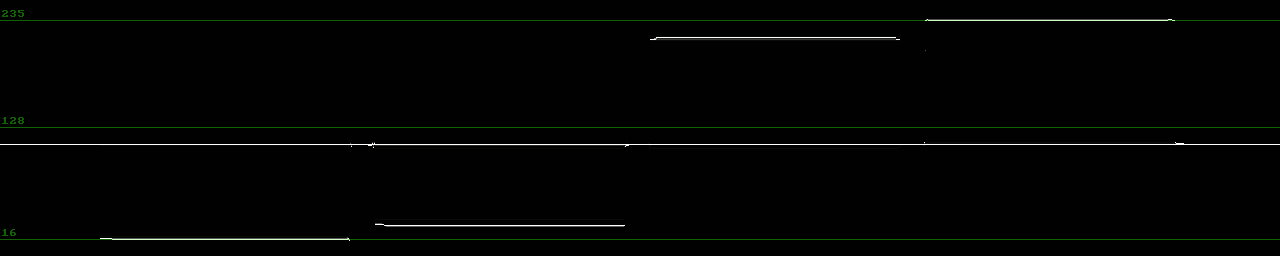
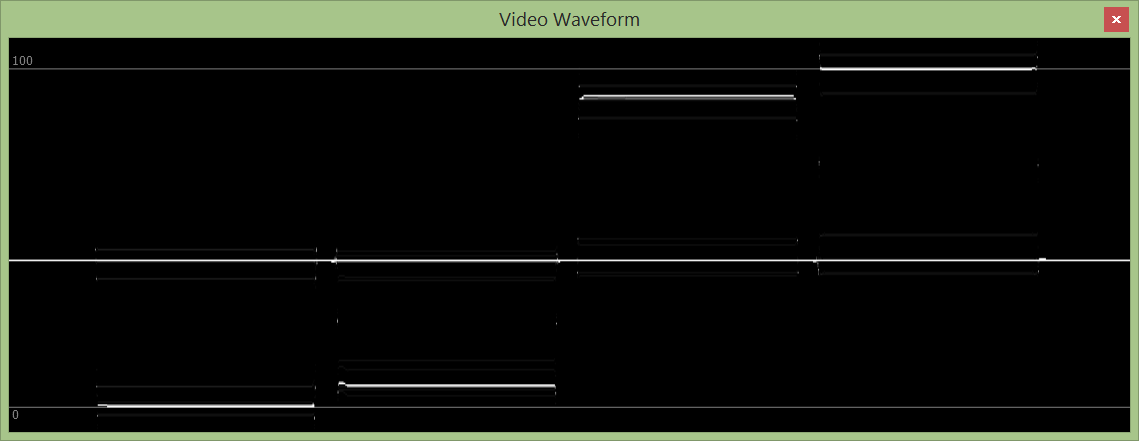
This means that the Shotcut scopes will show Y 255 as 100 IRE for full-range YCbCr, and Y 235 as 100 IRE for limited-range YCbCr, and RGB 255 as 100 IRE for any sRGB input file. This is correct in all cases, because those values represent maximum white (technically maximum voltage) within their specifications. An IRE waveform shows relative voltage, not absolute digital Y values. Y-value waveforms do exist, but this is not one of them. It would be incorrect to label Y 235 as 100 IRE when working on full-range video because Y 235 in full range has yet to reach the white point (maximum voltage).

Since 100 IRE (100 percent voltage) renders as the same white color (CIE D65) regardless of the range, we end up with a waveform graph whose Y-axis has fixed units from 0-100 IRE, but the resolution of the Y-axis is higher in full range (256) vs limited range (220). This requires scaling the waveform if switching ranges, and is why an IRE waveform must change in accordance with how the video is flagged. Technically, a Y-value waveform changes with the flag too by moving the graticules representing black and white points.

Using IRE for the waveform is a convenient way of showing in-gamut max white to max black, which is very useful and portable across sane color spaces. Granted, it’s not perfect because RGB by nature doesn’t have a luminance component. A conversion is happening to plot RGB video on a waveform, but it’s plenty good enough. Now, the day we get another color space where black is something other than 0 mV (0 IRE), then the graticules would land in different places and that would get annoying. But for now, the current waveform is a good “percentage brightness” meter that’s accurate across all supported color spaces. We actually need “percentage brightness” more than we need literal IRE or absolute Y-values when it comes to color matching clips to each other, especially if clips are from different color spaces or bit depths.

So, to say that BT.709 Y 235 = 100 IRE is only half the information. Is it limited or full range YCbCr? BT.709 specifies both. Therefore, color picking RGB 255 off the screen could translate to Y 255 in full range or Y 235 in limited range. Both are valid conversions. Which one is actually in the source video? Having a conversion in the chain (plus ambiguity) is precisely why color picking display-converted RGB values is prone to errors and says nothing about the true YCbCr stream underneath. For a scary example, consider a limited-range YCbCr file that has an overshoot Y 255 in it. Since Y 235 is max white in limited range and 255 was specified, the converted color will be a superwhite with over 100 IRE. But a superwhite can’t be represented on an sRGB display because it tops out at RGB 255. There is no RGB 278 option when Y 255 gets expanded out of its limited range. Therefore, due to clipping, a color picker will only see RGB 255 at most, and not realize that the underlying YCbCr stream had a superwhite. This is especially bad news for broadcast legalizer compliance checks, because supers would pass through unnoticed.

Conclusion

The Shotcut video zoom and waveform scopes are working as they should, and their current implementation is perfect for color matching clips from different color spaces and ranges. There is nothing to modify unless support is extended to color spaces with non-0mV black points, and then a percentage meter might become more useful.

Sources

[1] IRE definition
https://en.wikipedia.org/wiki/IRE_(unit)

[2] VGA voltage
http://microvga.com/faq/electrical/what-are-vga-voltage-levels

[3] ITU-R BT.709 official spec
https://www.itu.int/dms_pubrec/itu-r/rec/bt/R-REC-BT.709-6-201506-I!!PDF-E.pdf

[4] ICC interpretation of sRGB
http://www.color.org/sRGB.pdf

[5] sRGB official spec (IEC 61966-2-1)
https://webstore.iec.ch/publication/6168

1 Like

As he pointed out , your first video “window_signal.mp4” was Y=16, 30, 218, 235 ; not 0,16,235,255 as you described. Go ahead and check with ffplay or other tools

shotcut’s waveform works ok with videos flagged as limited, or unflagged, with over/undershoots, such has broadcast, BD, DVD, typical web video . As you know, those are never “full range” anyways (black level at Y=0, white level at Y=255) , but they do have under/overshoots

Full range flag changes the way it handles the video (even if original Y values are the same), and that is reflected in the waveform.

Austin: There is one detail missing from your explanation.

The decision to use 16-235 or 0-255 is not an arbitrary one — there is a valid technical reason for it. In ATSC, the standard for HDTV in the U.S., the digital values of 0 and 255 are reserved for sync and are strictly off limits for video information. The range from digital 1 to 15 is called “footroom”, and from 236 to 254 is called “headroom”. This was done to allow for over- and under-shoots and ringing caused by filtering and subsampling. This is moot if your video is going no further than YouTube, but if you’re making commercials or shooting news footage which might make it to broadcast, it is a concern. ITU BT.601 may have an explanation of this. BT.601 is now obsolete but was the bridge between analog and digital video.

I don’t know how many times I have to repeat this, but the video I attached is flagged as LIMITED RANGE. The ffplay scope and the Shotcut scope do not agree on what level is 100 IRE looking at the SAME VIDEO. Explain that. As the saying goes, “the man who wears two watches does not know what time it is.”

As far as I’m concerned, the ffplay scope is accurate for reasons I have stated multiple times.

For the hundredth time, I checked the levels and described how I did it, and got 0,16,235,255. I also checked that same file using ffplay scope. Why is it so hard for you to understand this and I have to explain it over and over again? Whatever he used to check the levels was clearly compressing 0 - 255 to 16-235.

So far in this discussion nobody has accounted for the discrepancy between the ffplay scope and Shotcut’s scope on the SAME VIDEO.

The first video you posted window_signal.mp4 (notice the underscore) has actual values of Y=16,30,218,235. I don’t know what you’re looking at; FFmpeg/FFplay waveform definitely does not show 0,16,235,255 . (I checked with other programs too)

ffmpeg -i window_signal.mp4 -vf waveform=g=green:o=0.25 -frames:v 1 window_signal.png

For which video? I already explained it above when you have limited range flag vs. full range flag and why you get the results you see

For your first video, Shotcut looks the essentially same as ffmpeg, because it has a limited range flag, (although they are IRE units)

I’ve explained it as much as I can. If you don’t understand after all the explaining I’ve done then I can’t help you.

These concepts are child’s play for someone with hands-on video engineering experience.

You just made a bad assumption, that’s all. So you’ve arrived at the wrong conclusion

You said you’re ok with the ffplay scope. We can agree on that
So run the scope in ffmpeg, what do you see ?

ffmpeg -i window_signal.mp4 -vf waveform=g=green:o=0.25 -frames:v 1 window_signal.png

I’ve posted the screenshots above, are you saying you get something different ?

When you use a RGB color picker, you ‘re in for a world of hurt if you don’t understand how the YUV<=>RGB conversions are being done in the background. YUV picker, or true Y’ waveform is simpler because it measures the levels directly, and you don’t get rounding errors or make as manhy wrong assumptions

On a web browser interface, computer RGB is used. Because it’s a computer. Y16-235 => RGB 0,0,0-255,255,255.

The patches show RGB 0, 16, 235, 255 because the Y values are 16,30,218,235

I’ll explain it another way to you, again , as I have before many times in other threads and forums.

You’ve said before , you’re ok with ffplay.

Since you like using RGB color pickers, recall ffplay - and studio range RGB would use

ffplay -i window_signal.mp4 -vf scale=in_range=full
The color picker shows RGB 16,30,218,235

Computer range RGB would use
ffplay -i window_signal.mp4
The color picker shows RGB 0,16,235,255 ; just like the what is shown in the browser. ie. the browser is using computer RGB

Recall that studio range RGB is your “unity” that we discussed many times before .The Y level <=> RGB level. 0-255 <=> 0-255. In ffmpeg you use the full range equations in/out

So if you’re ok with ffplay using studio range RGB; a result of RGB 16,30,218,235 would give a Y value of 16,30,218,235 .

Give it a rest, dude.

@Austin Thank you so much for this incredibly informative explanation.

If you have the time/interest, it would be incredible to adapt some parts of that write up into the documentation sections:

and

This is a critical distinction that applies to Shotcut. When Shotcut operates on YUV, it operates in limited-range. When Shotcut operates on RGB, it operates on full-range. I think this meets most people’s expectations. But it may not meet the expectations of people who come from a deep broadcast TV background.

Can you elaborate on this specific point? When I look at BT.709, Table 4.6 shows the quantization levels:


It doesn’t seem to leave any provision for full range.

I think it would be more accurate to say that BT.709 describes limited-range signals and sRGB (IEC 61966-2-1:1999) describes full-range signals. Maybe you have a better understanding of where full and limited range values are defined.

Thanks again for your thoughtful response on this topic.

I can demonstrate from source code that the ffmpeg/ffplay waveform filter is broken for full-range video. It is fine for limited-range video. See the GitHub link below for details.

Regarding other discrepancies, there’s the issue of the Shotcut scopes not showing the actual data that’s inside the input files. Rather, the scopes are showing data of the timeline’s preview output, which reports YUV in limited range regardless of the input file. The scopes must be interpreted in that context.

For sake of clarity, here are all combinations of scope output. Do these match your findings, and do you feel any of the scopes are reporting incorrect values? To be honest, I’m very hazy about which combinations are actually under scrutiny.

Y 235 with limited flag

  • Shotcut: 100 IRE, Y 235
  • FFmpeg: 100 IRE

Y 235 with full flag

  • Shotcut: 91 IRE, Y 217
  • FFmpeg: 100 IRE << wrong: Y 235 in full range has not reached white point, so is not 100 IRE

Y 255 with limited flag

  • Shotcut: 108 IRE, Y 255
  • FFmpeg: 108 IRE

Y 255 with full flag

  • Shotcut: 100 IRE, Y 235
  • FFmpeg: 108 IRE << wrong: Y 255 in full range is equal to white point, not greater

Shotcut appears to be correct regarding IRE in all cases. Shotcut’s Y-values are also correct if allowance is made for them always being stated in limited range. FFmpeg shows incorrect IRE values in full range due to hard-coded values. Y 235 does not automatically equal 100 IRE. 100 IRE is defined as the maximum voltage, which is the white point for BT.709. In full range, Y 255 is the white point, not Y 235. So FFmpeg gets IRE wrong by hard-coding equality between Y 235 and 100 IRE.

I have been unable to make Y 255 flagged as limited range appear as 100 IRE on the Shotcut waveform. The waveform has to be expanded very, very tall on the screen in order to see the overshoot, but it’s way up there as 108 IRE where it should be.

I need to use better wording. Thank you for the catch. I will update my post to say that BT.709 specifies full and limited range equations rather than signals. Only limited range is defined as a signal for transmission. But the YCbCr equations operate in full range up until the point they are compressed to 16-235/240 for transmission.

This distinction caused a lot of confusion earlier in this thread when the equations in table 3.5 resulted in “out-of-bounds Y 255” rather than Y 235 for white. It’s because this part of the chain is in full range. It is completely acceptable to write these full-range YCbCr values to a video file and call it BT.709 encoding provided it is flagged as full range. But it’s not legal to use full-range values for over-the-air transmission. That’s a different part of the chain.

My goal was to demonstrate that YCbCr can exist with either full or limited values depending on where in the equation chain the math is being done. Therefore, range must always be specified to properly decode YCbCr or communicate values to someone else.

I’m game. I don’t know what adaptations would be involved, so you’re welcome to slice and dice as you see fit. Or recommend changes and I’ll try to rewrite it. Whichever.

I covered it, although with less detail since the post was getting long. See:

Finally, here is the source code showing hard-coded values in the FFmpeg waveform filter. The graticule lines are defined in four columns which represent four components of a video signal: Y, Cb, Cr, Alpha. Line 2523 shows the YCbCr channels have 100% graticules hard-coded for 16-235/240 limited range. (The 255 is for Alpha.) The code never adapts to 0-255 based on input range. This is not the right way to calculate IRE, therefore it is wrong for full-range inputs. Y 255 in full range is the exact same color as Y 235 in limited range (they’re both the white point), so both represent the same voltage (the reference white level) and are therefore both 100 IRE.

Perhaps for an IRE definition; but this is not is not “wrong” when you use digital units 0-255 in Y, such as the default setting when using -vf waveform

Another way to think of it is that the waveform examining the raw Y data directly. The flag does not affect the actual raw, it’s just metadata

But scaling based on a flag implies some transformation is applied afterwards, such as for conversion to RGB, or Y adjusting of levels. That’s not necessarily the actual original Y values in the bitstream or the original video. eg. If you were to decode to elementary .yuv videostream, and look at the hex data. And that’s ok if that’s how the data is changed in a video application such as a video editor, you’re measuring the transformed output data, not the original data

Measuring digital units of the input file is “pure”, exact. That does not rely on what context something is being used in , or how some program decides to interpret something. There are no rounding errors are other errors introduced. Also, videos can be unflagged, or flagged improperly. But the raw data is always correct what reflects what the actual code values are

Austin’s statement gave me pause but I didn’t dispute it right away. Brian is right: BT,709 does not make provision for “full range” 0 - 255. I gave a detailed explanation for this, but to refresh memories, the values 0 and 255 are reserved for sync and are off limits for video information. If video information extends to 0 or 255, it’s going to freak out parts of the signal chain that depend on a source of sync at 0 or 255.

How does this flaw manifest itself?

Digital units are unambiguous. ffplay offers the option of either digital units or IRE units. Shotcut offers IRE units and that’s it — no digital units. If the Shotcut scope offered digital units, this would be a definite improvement.

There are many video players that alter the video levels. For example, a 235 pixel is made 255 or 255 made 235, so you don’t get a true visual representation of the data in the image. This may be acceptable to the YouTube crowd but not for critical users; not just broadcast but theatrical and other high-end applications. For example, if you have and area of, say, 235 next to an area of 255 and the player messes with it, making 235 into 255 or 255 into 235, the two areas will become indistinguishable and you lose detail.